Weather Observation with Raspberry Pi – Vol2 Cutting
Making cases for the circuits is a big job!
Buying cases and circuit boards
I walked through Akihabara and found a case that seemed to enough big to have a pi and circuit board. This is a Takachi TD9-12-4N, an aluminum case sold for JPY 820 (USD7.00).
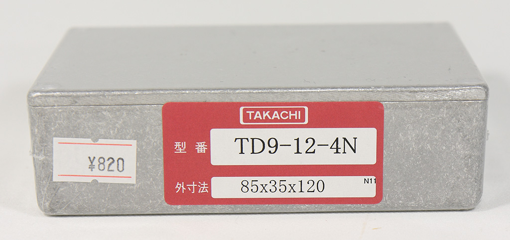
Takachi TD-9-12-4N
I chose an ABS plastic case Takachi SW-50 for the probe case. It was sold for JPY 100.
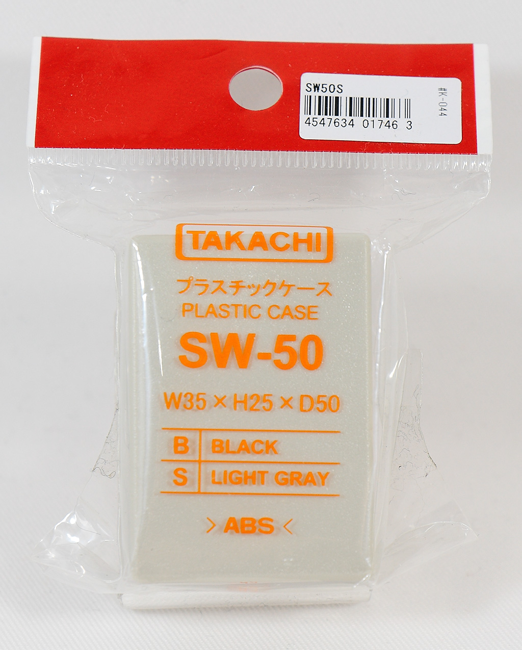
Takachi SW-50
I chose a TB-17. This board is for circuit for Raspberry Pi. It is enough big to have all the GPIOs.
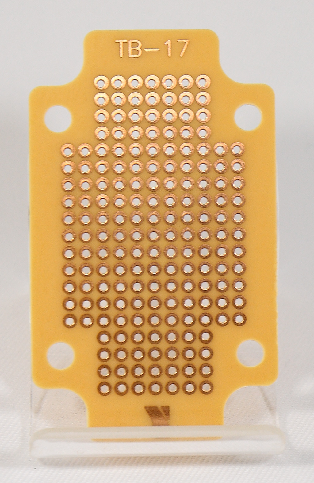
TB-17
I noticed later that I could make boards on my own. This is advantage when I choose cases and circuits. This board is sold at Sengoku Densho.
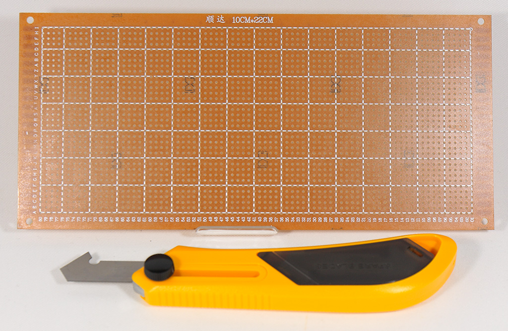
Circuit Board and Knife
The knife below is an Olfa PC-L plastic cutter. This is a knife to not “cut” but “scratch”. After scratching 3 to 5 times, then you can split. This knife is better than normal knife.
Designing
I put them in the case and imagined where to place.
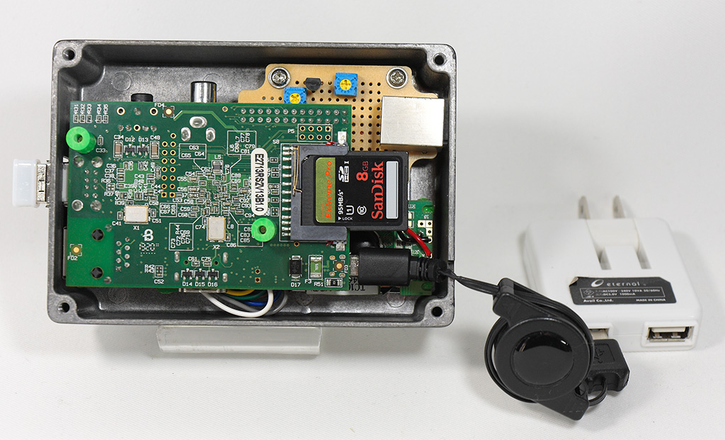
All in Case
In the picture they are made already, but before that I had them in my hand and spent time just to imagine if they fit or not.
I showed the PCB view in the previous post, but actually I went to the circuit and the case back and forth. At last I got the circuit.
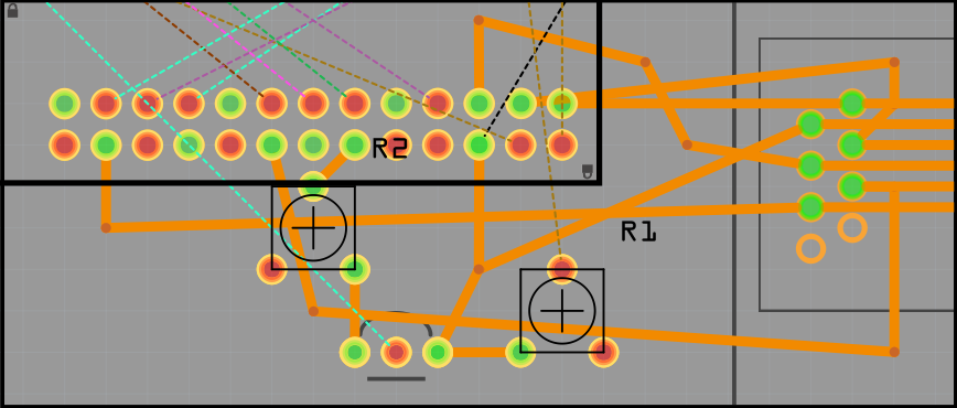
PCB Pi Case

PCB Probe Case
Drawing and Drilling
I designed the Pi case and the circuit again with drawing software. I used slide calipers and drew in the actual size. And then printed the drawings and put them on the box.
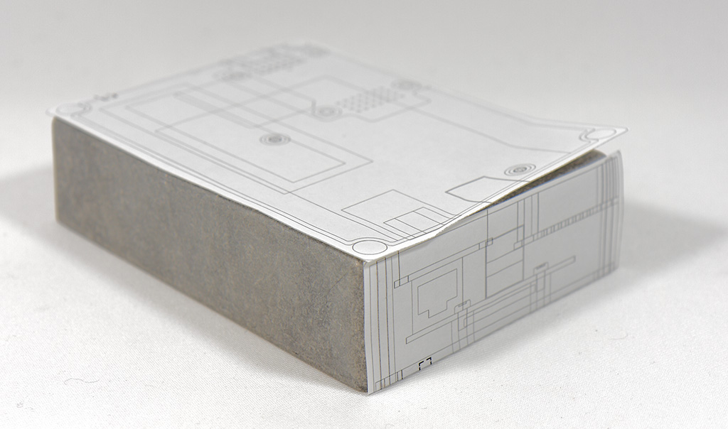
Aluminum box and the drawings
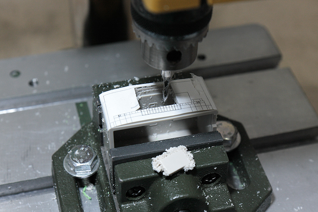
I fixed on the milling machine.
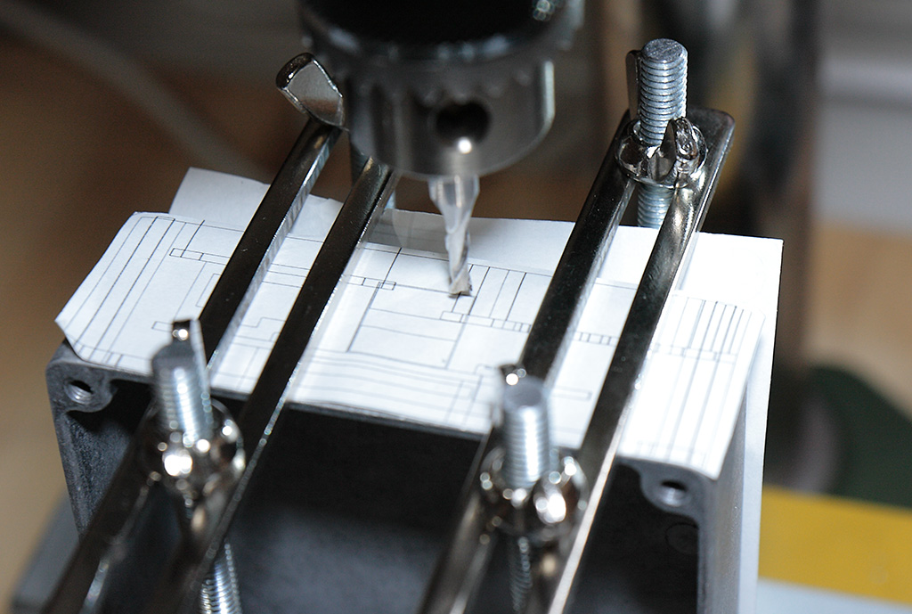
Case and milling machine
Read “Making and studying an Akizuki Triac Dimmer (speed controller) and case processing” about the milling machine.
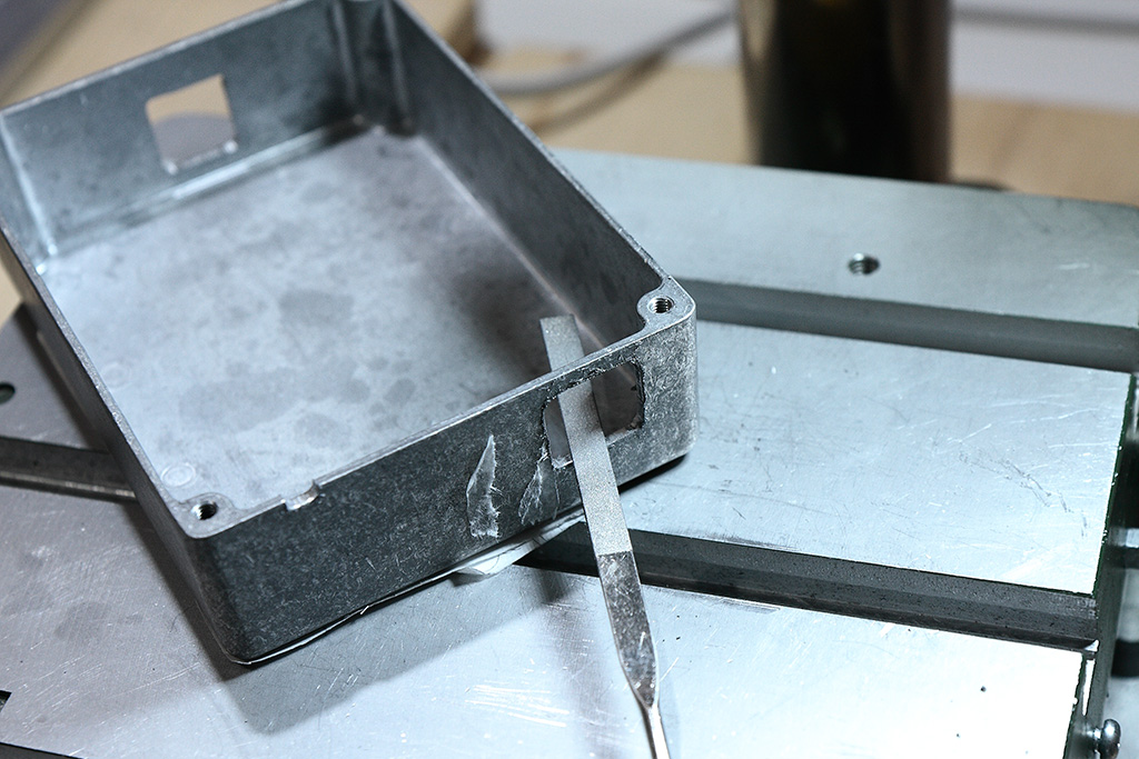
Removing burr
I opened a window for LCD.
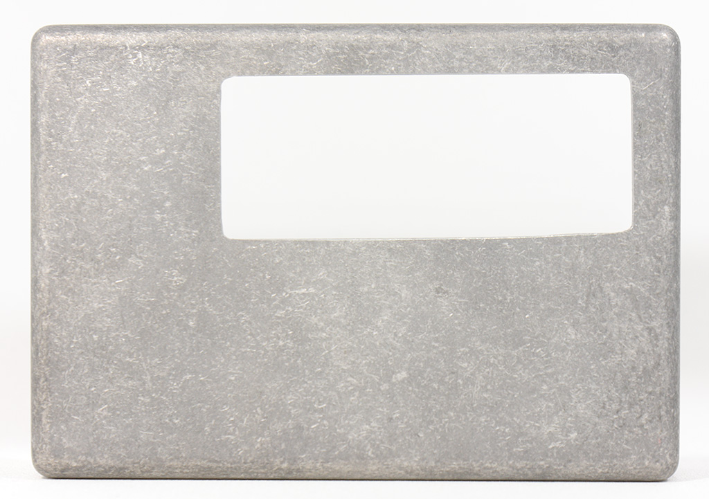
Main Case and LCD Window
The window is slanted because the screw of the stage of the milling machine was loose.
I drilled the circuit board too.
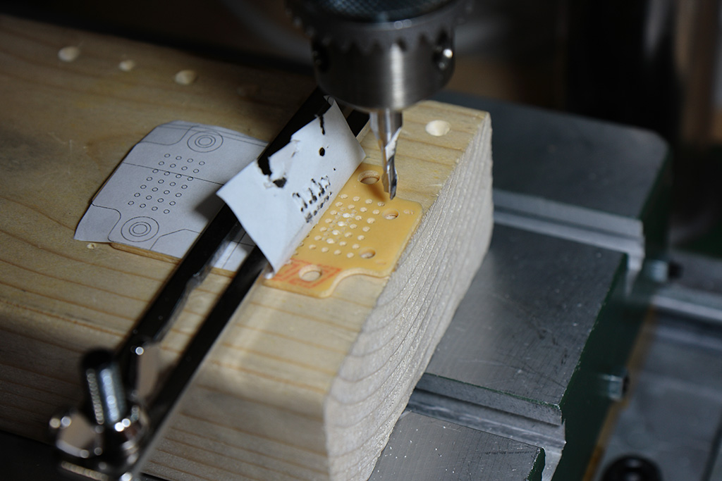
Drilling TB-17
And I put the jack.
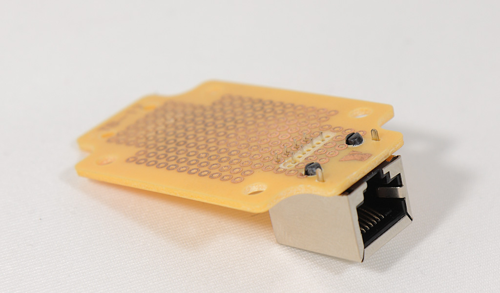
Extension Board After Cutting
RJ45 Jack’s pins are located irregularly. They have 4 pins in 2 lows but pins in one low are shifted so that they don’t fit in the holes. I needed to make 4 new holes for those pins. And then drilled slightly to remove copper to prevent touching.
I drilled 4 more holes for legs. The metal legs are 1.5mm wide, and the plastic legs are 2.4mm wide. I think the size of the hole should be 0.1mm or 0.2mm larger than the legs. I opened 1.6mm and 2.5mm.
Drill Bits
I used these drill bits.
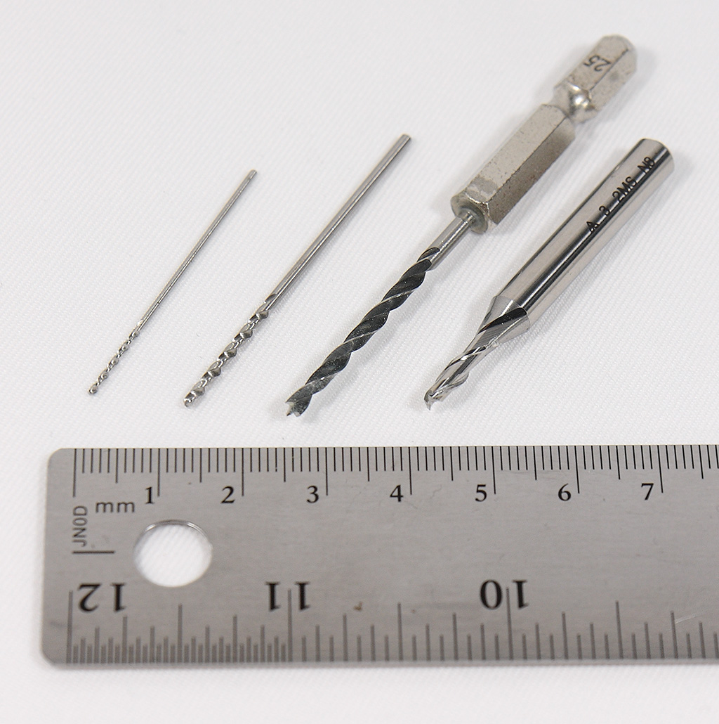
Router Bits
| Mfr | Name | Size | Product |
| Mitsubishi Material | Drill bit for stainless steel | 1.0mm | B-KSD 1.0 |
| Mitsubishi Material | Drill bit for stainless steel | 1.6mm | B-KSD 1.6 |
| RELIEF | Drill bit for woodwork and resin | 2.5mm | 26359 |
| Proxxon | Endmill | 3.0mm | 20613 |
Look carefully and you will notice they have different shapes of edge and body. The first 3 drill bits are to make holes. I use stainless steel because I bought already. They are hard enough to make holes on steel, but the problem is the drill bit bends about 1mm when the edge touches the object. This doesn’t happen if you use a drill bits like the third one.
Endmill is a drill bit not only for making holes but also cutting. The problem is it is short.
Now l go back to work. The probe case is drilled in the same way.
Opening a window for the probe case
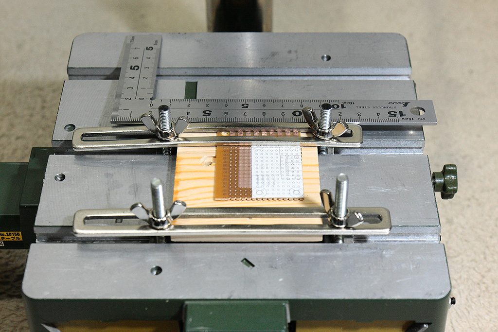
The circuit board for probe is set
Make sure the board is set at right angles.
I made spacers too.
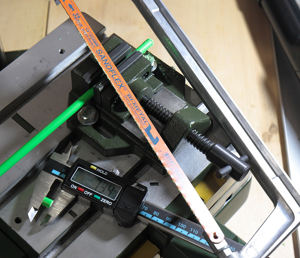
Cutting an ABS Bar
You do not need to make them. Just buy M3 spacers because all the screws used in the electric DIY seem M3 as far as I have seen. I made by myself just for experience. It should be an advantage to make spacers whatever size I want.
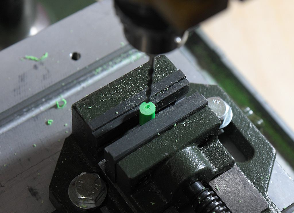
Drilling ABS Bar
I needed to find the exact center. The drill bit I mentioned before is useful here because the cut of the bit marks a center dot and a circle.
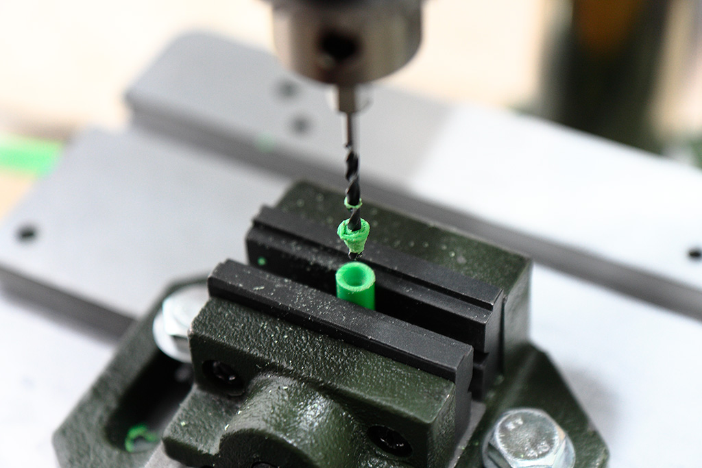
Drilling ABS Bar
If you drill too fast, this happens. Can you tell what happened in this picture? The friction produced heat, and it melted. Because I moved up and down, the melted part froze and stuck, and became a part of the bit. And then that made the hole bigger!
After opening a 2.5mm hole, I engraved inside to make a female screw. To do so is called “to tap”. To tap you need a tap and a tap holder.
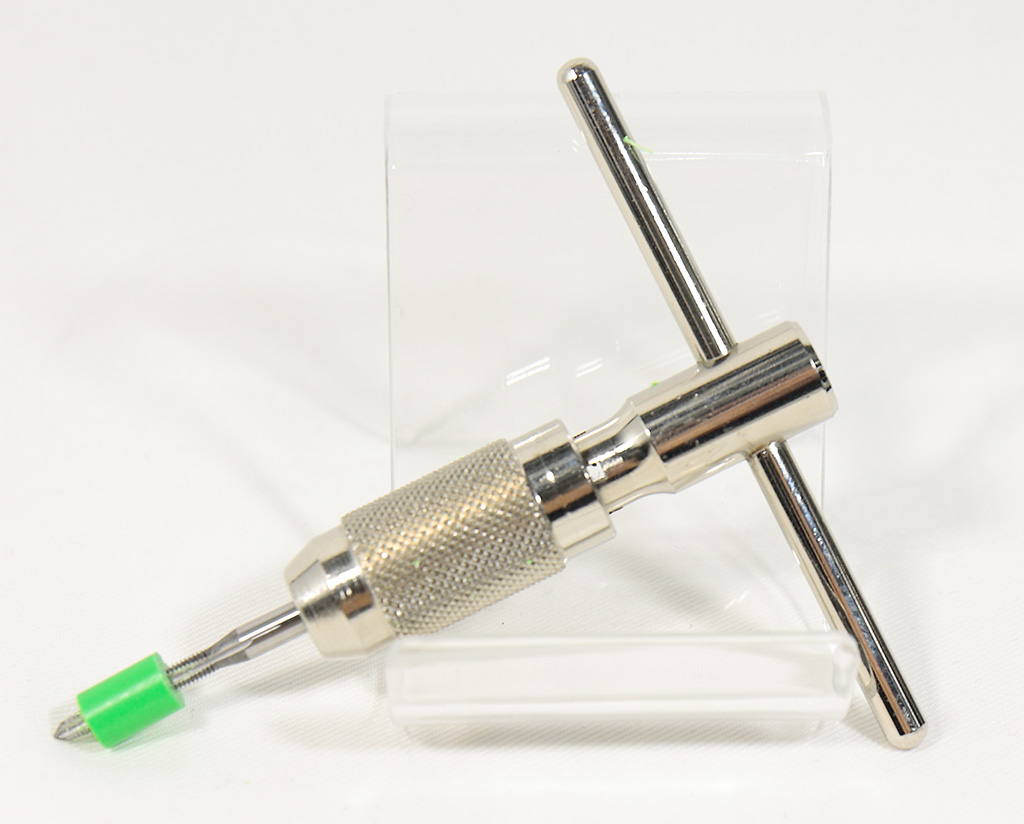
Tap and tap holder
Read “Making and studying an Akizuki Triac Dimmer (speed controller) and case processing” about tapping.
The story continues to “Weather Observation with Raspberry Pi – Vol3 Soldering“
This post is also available in: Japanese
Leave a Reply