Weather Observation with Raspberry Pi – Vol1 Circuit
I made a Weather Observation Machine with a Raspberry Pi and it is running for one year!
Making a logger by myself
When I was in Puno, I was wearing a black sweater on the street where the temperature was above 100 Fahrenheit! (40 Celsius degrees) But I didn’t even have sweat. What I was wearing was not a sweater? (LOL) Read “Peru Trip and Altitude Sickness” for the story.
Unusual experiences in Puno were enough for me to consider logging temperature, humidity and air pressure of my room. I searched with the word “humidity logger”, and found some products, but I didn’t want to buy them because they were expensive and I needed to spend extra time or to buy extra software to convert data to my computer.
And then, I met Raspberry Pi. Read “A total beginner started to learn electronics with Raspberry Pi“. And After learning some electronics stuff I could measure humidity with a Pi. Read “Drive RHT03 with Raspberry Pi” about the story.
After that, I kept using them in this form.
Pi and RHT03
I couldn’t develop next. So I bought another Pi and let it concentrate on weather observation. I also bought an LCD so that I could know the latest result immediately. Read”Drive SC1602 and SC2004 with Raspberry Pi” for LCD.
Humidity and air pressure
It is hard for Japanese to imagine the situation in Puno because Japan is always humid. They don’t think humidity is another important factor that connects to how we feel. Our summer is not only hot but steamy!
Air pressure is power that shows how much air is condensed by gravity. Because air is invisible, it is hard to tell.
This is a bag of wet tissue I took with me to Puno. The bag shows air pressure on the ground and Puno are different, but why does the bag expand? It is confusing, isn’t it?

Tissue Package
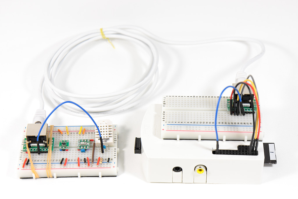
Things I bought
I decided to put things into 2 boxes. The Pi box has a Pi, SC1602 (LCD), a LAN jack, and so on.
| Parts | Product Number | mfr. | Reseller |
| Raspberry Pi | B | Raspberry | click here |
| SC1602 (LCD) | TC1602E-06T | Linkman | Marutsu |
| LAN Jack (RJ45 Jack) | 3010S-880 | Linkman | Marutsu |
| Circuit board | TB-17 | Teishin | Sengoku Densyo |
| Case | TD9-12-4N | Takachi | Marutsu |
| Potentiometer 10KΩ | GF063PB103 | TOCOS | Sengoku Densyo |
| Transistor | 2SC1815 | TOSHIBA | Akizuki Denshi |
| 2×16ピン | Various | Various | Various |
Oh, they stopped making Raspberry Pi B… Other versions of Raspberry Pi should be used if you use the same GPIO numbers.
The probe case has a RHT03 (humidity sensor), a MPL115A2 (air pressure sensor), a LAN jack, and so on.
| Parts | Product Number | mfr. | Reseller |
| Humidity sensor | RHT03 | MaxDetect | Sengoku Densyo |
| Air pressure sensor | MPL115A2 | freescale | Marutsu |
| LAN Jack (RJ45 Jack) | 3010S-880 | Linkman | Marutsu |
| Circuit board | 10CM*22CM | Unknown | Sengoku Densyo |
| Case | TW4-2-5 | Takachi | Marutsu |
| Potentiometer 10KΩ | GF063PB103 | TOCOS | Sengoku Densyo |
| Transistor | 2SC1815 | TOSHIBA | Akizuki Denshi |
Fritzing
I used free software “Fritzing” to make the circuit. Even some parts are not translated into Japanese, it is wonderful software.
Fritzing has 3 views: Breadboard view, Circuit view, and PCB View.
Breadboard View
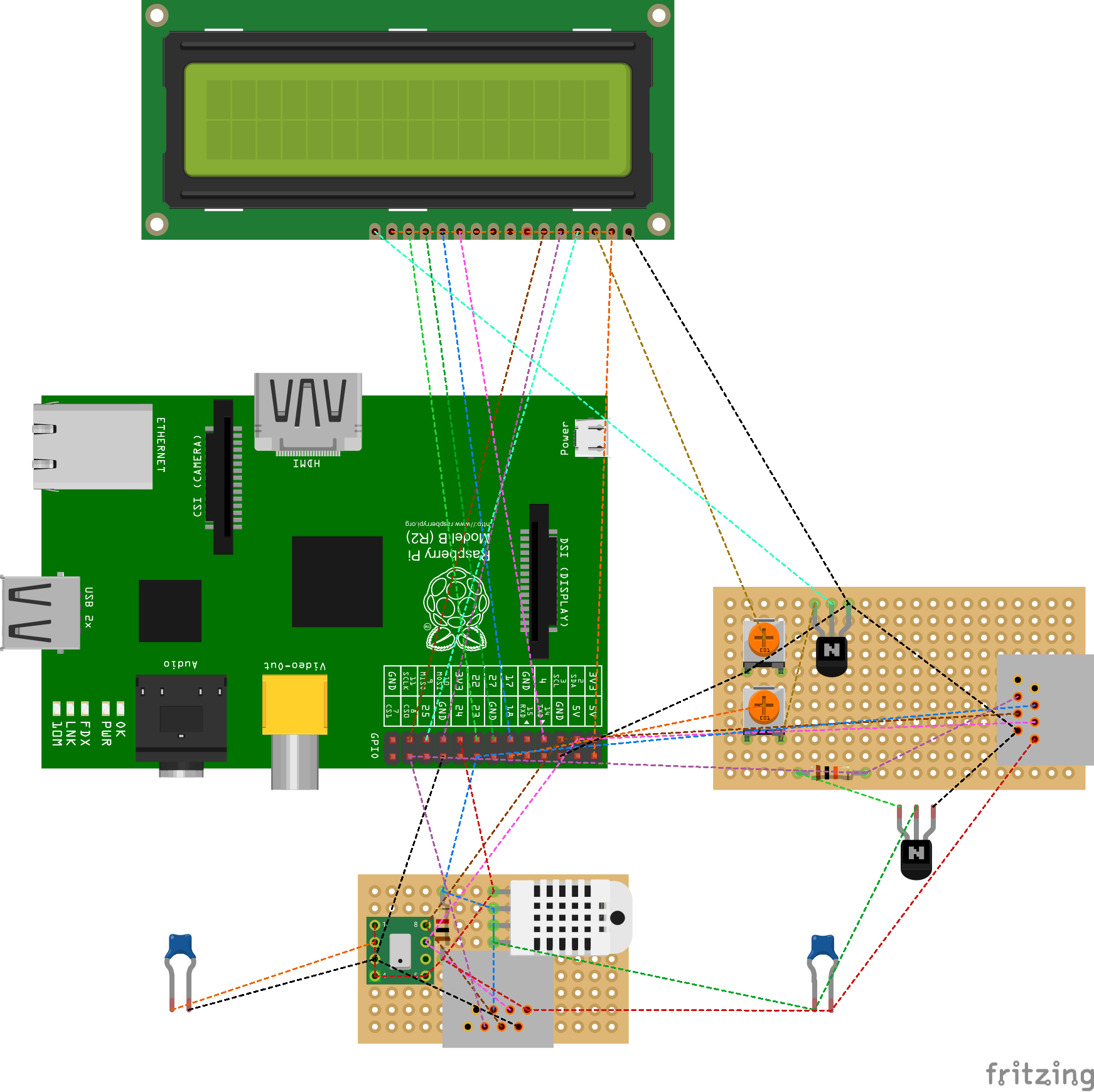
Breadboard View
The Breadboard view is the basic view of Fritzing. You can drag and drop components and wire by dragging one edge to another. I didn’t wire in this view, but lines are drawn automatically when I wire in the Circuit View.
Some components are floating, but they are OK because I edit the exact place in the PCB View.
Circuit View
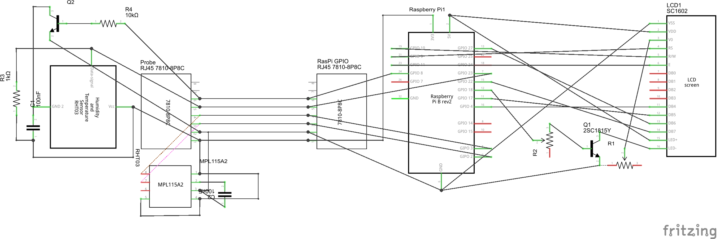
Circuit View
The Circuit View is where you actually connect pins. Drag a green edge to another edge.
PCB View
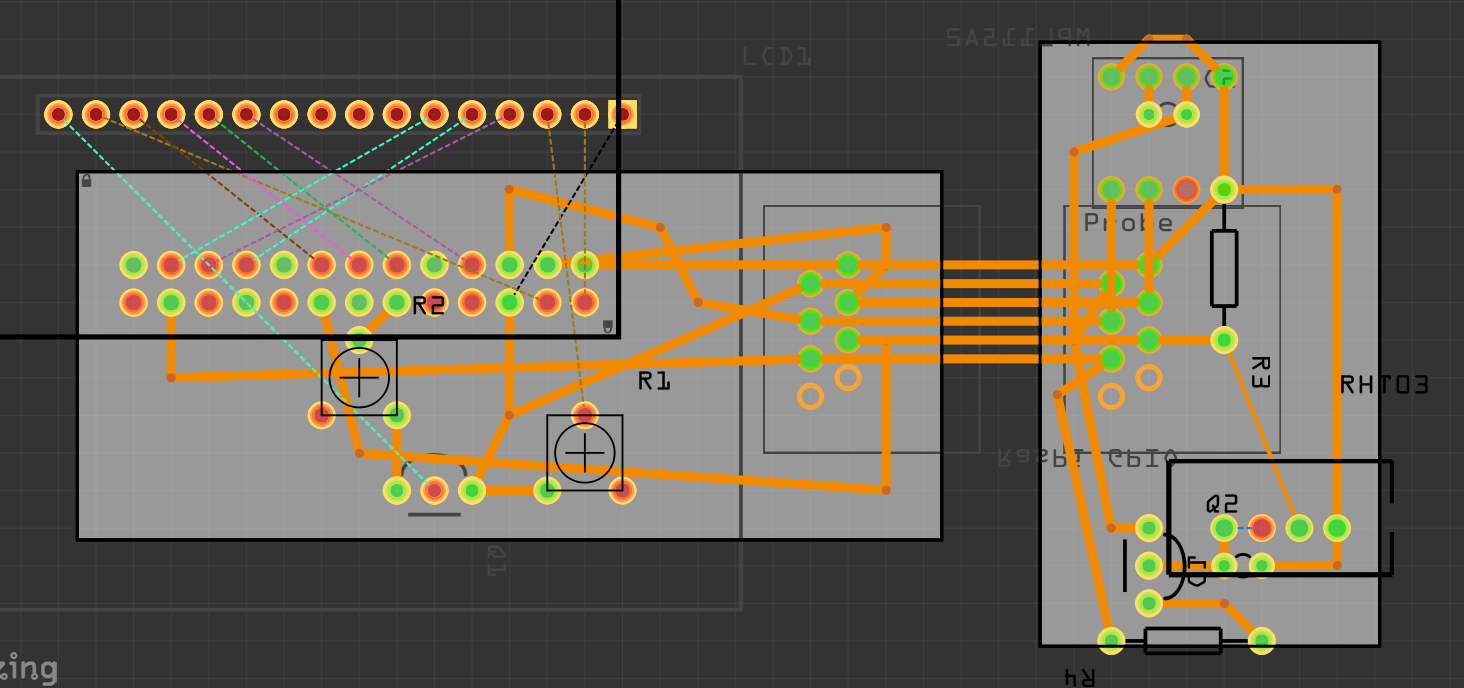
PCB View
The PCB View is used to design how to route the actual wires. Default wires are drawn automatically if you wire in the other views. Because PCB View is designed to make a PCB, all the wires are colored in the same color, which is a bit inconvenient to me.
You can turn PCB so that you can imagine the actual circuit.
Circuit for Pi
This is the circuit inside the Pi box.
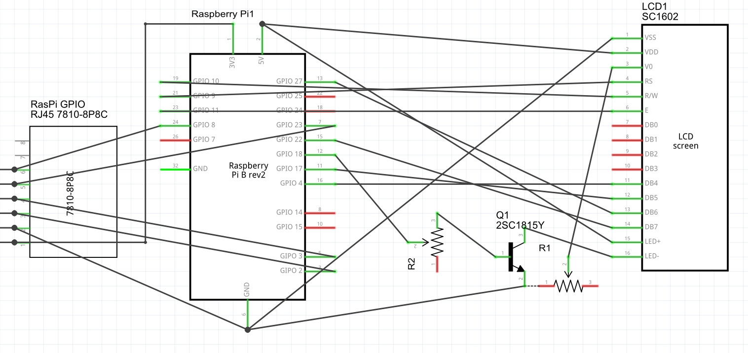
Circuit for Pi
There are 2 circuits. The circuit on the right side of Pi is to control SC1602. The circuit on the left side of Pi is just connection to the probe.
There are 3 groups of wires connected to SC1602. The first group is to control SC1602 itself. The wires are VDD, VSS, DB4 to DB7, RS, R/W and E. Read “Drive SC1602 and SC2004 with Raspberry Pi” for detail. The second group is to control the contrast of characters of SC1602. The wires are V0 (VO?). The third group is to control the backlight of SC1602. The wires are LED+, and LED-.
R1 determines the contrast of the SC1602. I didn’t consider controlling it from the Pi. If I did it, I would need to figure out a good way.
There are 2 ways to control backlight: brightness and on/off. R2 determines the brightness of the SC1602. I didn’t consider controlling it from the Pi too. I used GPIO18 to turn on/off the backlight. I wired so that when GPIO18’s voltage is high, up to 5V is added to the SC1602.
Circuit for Probe
This is the circuit inside the probe box.
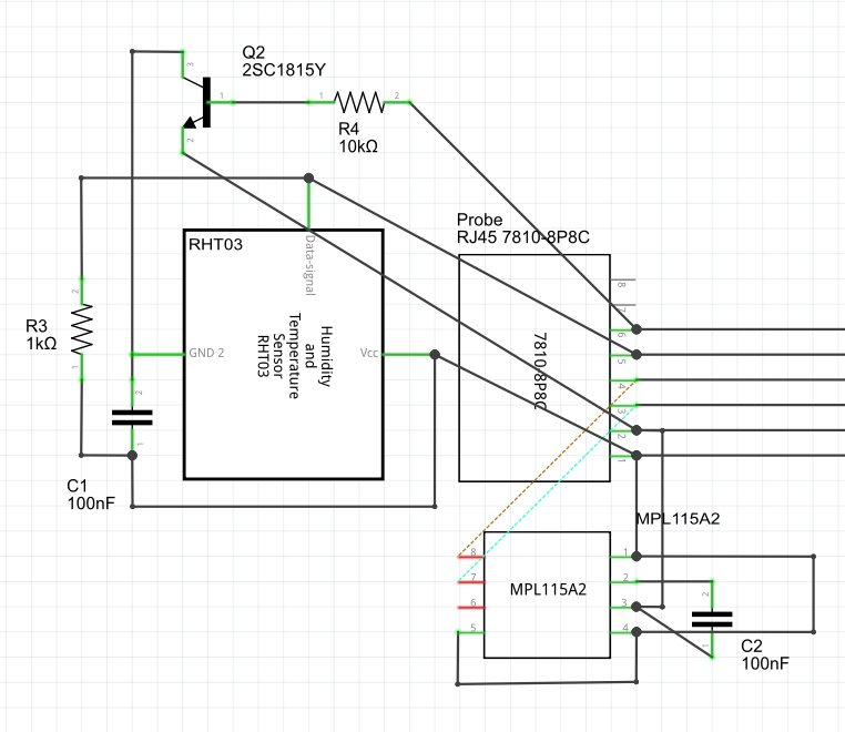
Circuit for Probe
These are connections to the Pi.
| No | Raspberry Pi | purposes |
| 1 | 3.3V | power |
| 2 | GND | GND |
| 3 | I2C SDA | MPL115A2 |
| 4 | I2C SDC | MPL115A2 |
| 5 | GPIO23 | RHT03 |
| 6 | GPIO8 | RHT03 on/off |
| 7 | – | Not in use |
| 8 | Not in use |
I just followed the instruction of MPL115A2 and RHT03. I added a transistor Q2 and resistor R4 to turn on/off RHT03. I did it because RHT03 stops working sometimes and recovers if I plug the power cable. I used GPIO8 exactly for the same purpose of GPIO18.
The story continues to “Weather Observation with Raspberry Pi – Vol2 Cutting“
This post is also available in: Japanese
Leave a Reply